ARDUINO UNO
ARDUINO UNO is a microcontroller board based
on the Atmega328P . It has 14 digital input/output pins (of
which 6 can be used as PWM outputs), 6 analog inputs, a 16 MHz ceramic
resonator (CSTCE16M0V53-R0), a USB connection, a power jack, an ICSP
header and a reset button
ARDUINO UNO KIT
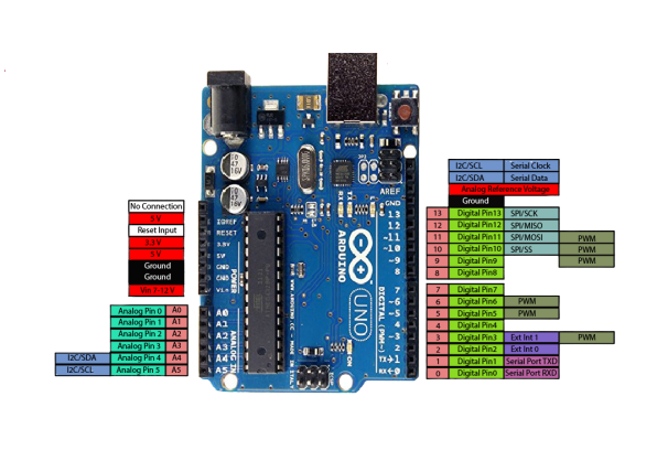
ARDUINO PIN OUT DIAGRAM
Arduino Uno Technical Specifications
| Microcontroller |
ATmega328P – 8 bit AVR family microcontroller |
| Operating Voltage |
5V |
| Recommended Input Voltage |
7-12V |
| Input Voltage Limits |
6-20V |
| Analog Input Pins |
6 (A0 – A5) |
| Digital I/O Pins |
14 (Out of which 6 provide PWM output) |
| DC Current on I/O Pins |
40 mA |
| DC Current on 3.3V Pin |
50 mA |
| Flash Memory |
32 KB (0.5 KB is used for Bootloader) |
| SRAM |
2 KB |
| EEPROM |
1 KB |
| Frequency (Clock Speed) |
16 MHz |
|
|
|
|
|
|
|
|
|
|
|
|
|
|
|
|
|
|
|
Pin Description
| Pin Category |
Pin Name |
Details |
| Power |
Vin, 3.3V, 5V, GND |
Vin: Input voltage to Arduino when using an external power source.
5V: Regulated power supply used to power microcontroller and other components on the board.
3.3V: 3.3V supply generated by on-board voltage regulator. Maximum current draw is 50mA.
GND: ground pins. |
| Reset |
Reset |
Resets the microcontroller. |
| Analog Pins |
A0 – A5 |
Used to provide analog input in the range of 0-5V |
| Input/Output Pins |
Digital Pins 0 - 13 |
Can be used as input or output pins. |
| Serial |
0(Rx), 1(Tx) |
Used to receive and transmit TTL serial data. |
| External Interrupts |
2, 3 |
To trigger an interrupt. |
| PWM |
3, 5, 6, 9, 11 |
Provides 8-bit PWM output. |
| SPI |
10 (SS), 11 (MOSI), 12 (MISO) and 13 (SCK) |
Used for SPI communication. |
| Inbuilt LED |
13 |
To turn on the inbuilt LED. |
| TWI |
A4 (SDA), A5 (SCA) |
Used for TWI communication. |
| AREF |
AREF |
To provide reference voltage for input voltage. |
|
|
|
|
|
|
|
|
|
|
|
|
|
|
|
|
|
|
|
|
|
|
|
|
|
|
|
|
|
|


Comments
Post a Comment